
Spray Center Electronics
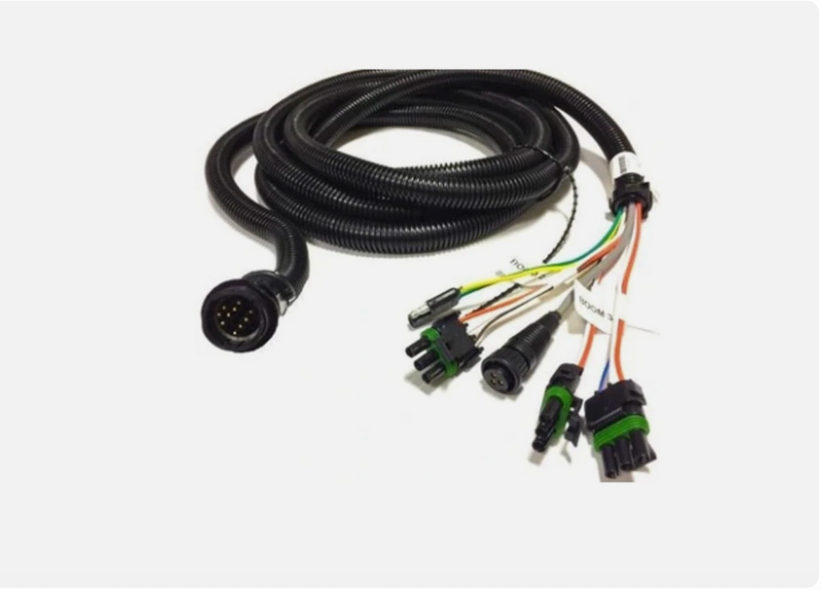
Raven Switch Pro 37-Pin Machine Cable (Custom Built) — Tractor Hitch to Sprayer
Raven Switch Pro 37-Pin Machine Cable (Custom Built) — Tractor Hitch to Sprayer
Questions on fitment? Need a different size or quantity?


Request a quote or ask about this part by email
The SCE 37-Pin Switch Pro Machine Cable is the implement-side half of a Raven Switch Pro installation: it picks up at the tractor hitch, where the 37-Pin Switch Pro Console Cable ends, and runs back along the sprayer to the valves and sensors the Switch Pro controls. Because it lives outside the cab, it is the cable that gets dragged, kinked at the hitch and soaked in fertilizer, so it is the one that usually needs replacing first. We build it to your boom and trailer length.
Custom built to spec in our Spokane, WA shop. Tell us the console, the tractor and the run lengths and we build it to fit; use the custom cable request form or call (509) 838-2209. Need a longer run? Add cable length per foot.
Works with
- Raven Switch Pro systems (Envizio Pro, Viper 4 / 4+ consoles)
Related
37-Pin Switch Pro Console Cable · Cable Check Out (bench test) · troubleshooting electric boom valves
Switch Pro 37-pin (J1) console connector pinout
This is the 37-pin connector on the Raven Switch Pro harness, as wired in our console and machine cables. The wire number on the drawing matches the pin number, so wire 28A is pin 28. The harness breaks out into six shielded sensor cables: CBL1 speed, CBL2 serial, CBL3 flow 2, CBL4 flow 1, CBL5 pressure 1, CBL6 pressure 2. Use it to check continuity end to end, to find which pin a dead boom section rides on, or to confirm power and ground before condemning the Switch Pro.
| Pin | Wire | Function |
|---|---|---|
| 1 | White 14 ga | Ground (−BATT) |
| 2 | Orange/White 14 ga | Remote master |
| 3 | Orange 14 ga | +12 V switched |
| 4 | Black 18 ga | Boom 1 |
| 5 | Brown 18 ga | Boom 2 |
| 6 | Blue 18 ga | Boom 3 |
| 7 | Black/White 18 ga | Boom 4 |
| 8 | Brown/White 18 ga | Boom 5 |
| 9 | Blue/White 18 ga | Boom 6 |
| 10 | White/Black 18 ga | Boom 7 |
| 11 | White/Brown 18 ga | Boom 8 |
| 12 | White/Blue 18 ga | Boom 9 |
| 13 | Pink 18 ga | Boom 10 |
| 14 | Violet 18 ga | Fan signal |
| 15 | Green 18 ga | Decrease (control valve) |
| 16 | Yellow 18 ga | Increase (control valve) |
| 17 | Shielded cable, red 22 ga | Serial RX (CBL2) |
| 18 | Shielded cable, white 22 ga | Serial CTS (CBL2) |
| 19 | Shielded cable, black 22 ga | Serial TX (CBL2) |
| 20 | Shielded cable, green 22 ga | Serial DTR (CBL2) |
| 21 | Shield / drain | Signal ground: flow 1, flow 2, speed and serial shields all land here |
| 22 | Shielded cable, black 20 ga | Flow 2 +5 V (CBL3) |
| 23 | Shielded cable, white 20 ga | Flow 2 signal (CBL3) |
| 24 | White/Green 18 ga | Bin level signal |
| 25 | Shielded cable, black 20 ga | Flow 1 +5 V (CBL4) |
| 26 | Shielded cable, black 20 ga | Speed +5 V (CBL1) |
| 27 | Shielded cable, red 20 ga | Speed signal (CBL1) |
| 28 | Shielded cable, red 20 ga | Flow 1 signal (CBL4) |
| 29 | Shield / drain | Pressure 1 and pressure 2 ground |
| 30 | Shielded cable, black 20 ga | Pressure 1 +12 V (CBL5) |
| 31 | Shielded cable, red 20 ga | Pressure 1 signal (CBL5) |
| 32 | Yellow 16 ga | CAN high |
| 33 | Green 16 ga | CAN low |
| 34 | Shielded cable, black 20 ga | Pressure 2 +12 V (CBL6) |
| 35 | Shielded cable, white 20 ga | Pressure 2 signal (CBL6) |
| 36 | Red 14 ga | +BATT (fused 15 A, F1) |
| 37 | Red 12 ga | +BATT (fused 30 A, F2) |
Pinout from the Raven Switch Pro harness wiring diagram as built by Spray Center Electronics. Shielded-cable drains (pins 21 and 29) are grounds, not signal wires: a shield that reads open to pin 21 will make a flow or speed sensor read erratically even though the signal wire tests good.
Details
| Product | 37-Pin Switch Pro Machine Cable |
|---|---|
| Connector | 37-pin, Raven Switch Pro |
| Runs | Tractor hitch → sprayer valves and sensors |
| Build | Custom length and routing, built to order |
| Built by | Spray Center Electronics, Spokane, WA |